Logical Design
In each scenario, any 10 clients in the building should be able to access any server at Gigabit speeds. In the first (left) design, each group has a 10gb link to their own server, and a 10gb link to the other servers (through the bottom 10Gb switch). The second (right) design, there is a 20Gb link to the main file server, so if multiple (more than 20) people are accessing this one, there will be less slow down. Design one however is more expensive than design two.
Costings Sheet
The diagram below shows 2 ideas, both using star topologies.
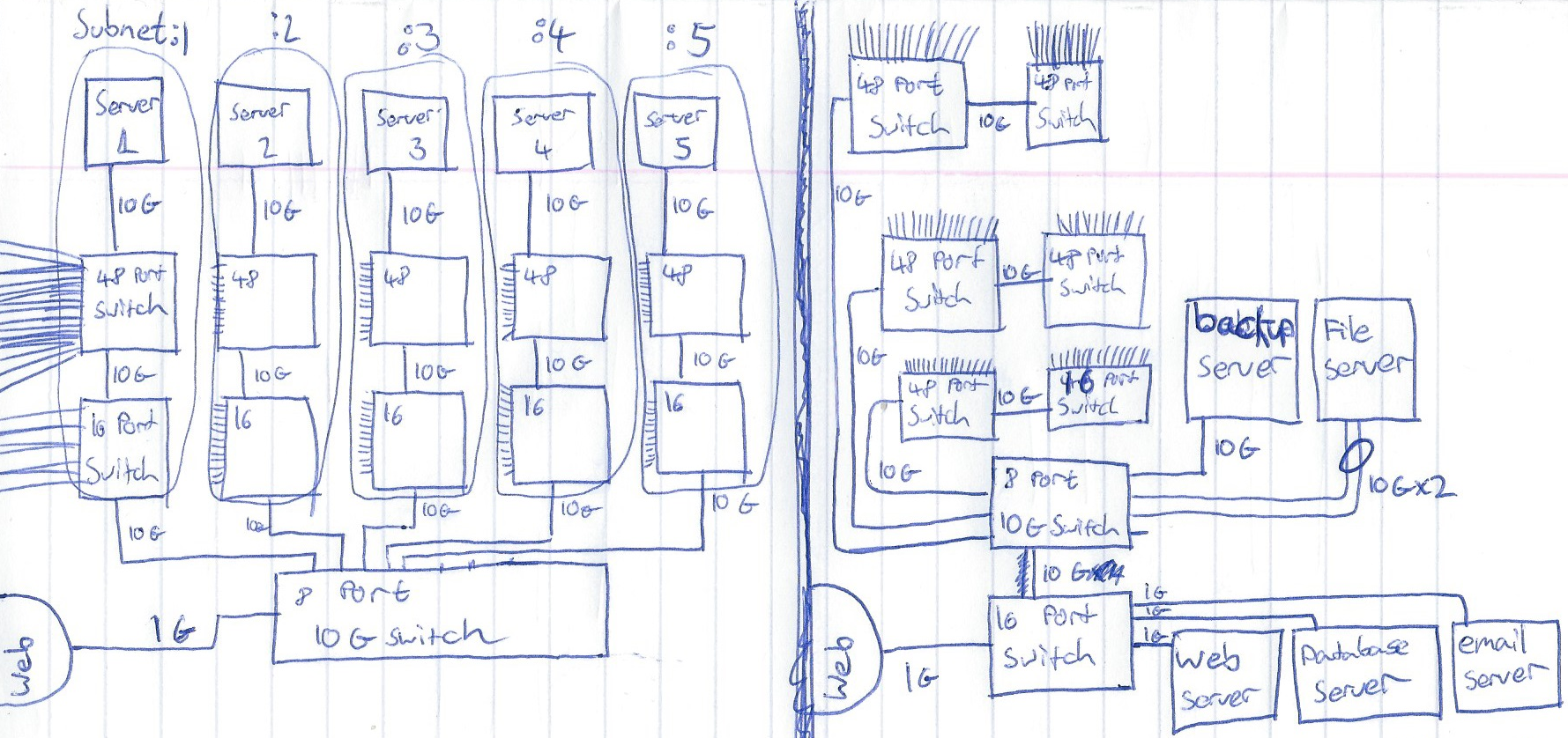
We have chosen to go with the diagram on the right, but will be modifying it because...
- No WiFi APs
- There is a single point of failure.
- Link aggregation on the File server is not recommended
Here is the new Logical Design with WiFi APs and redundant core.
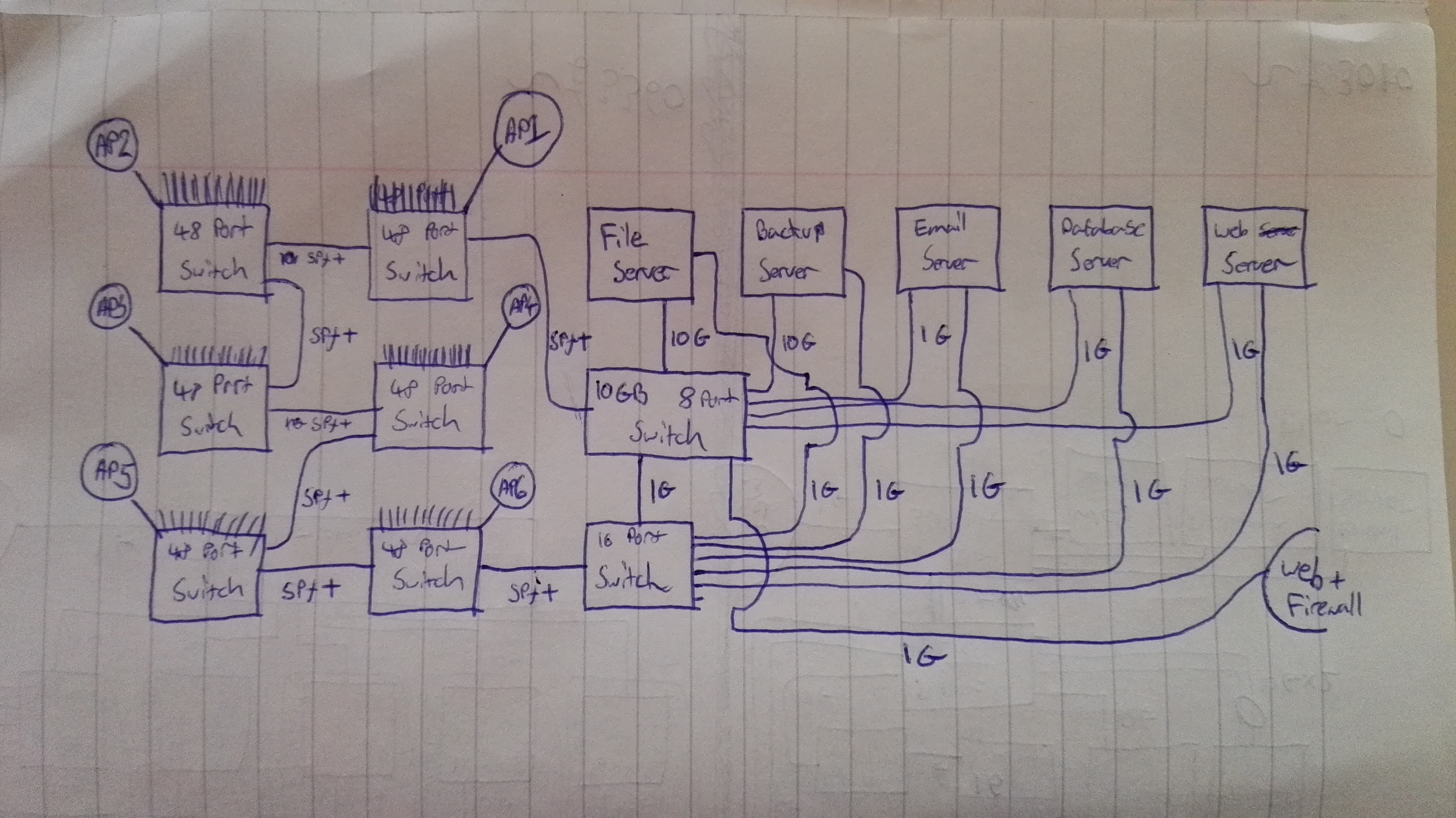
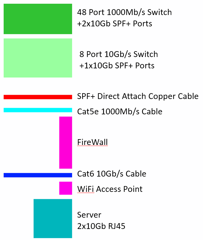
We later revised this for more redundancy, and to add the 7th switch. (situated on the middle floor)
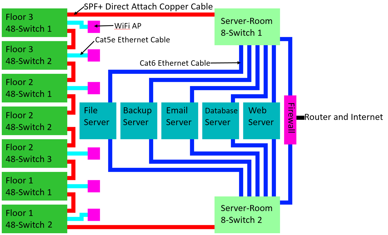
Here is the key to the diagrams below.
Physical Design
Here is the key to the diagrams below. Any equipment not on the diagram are inside the server rack.
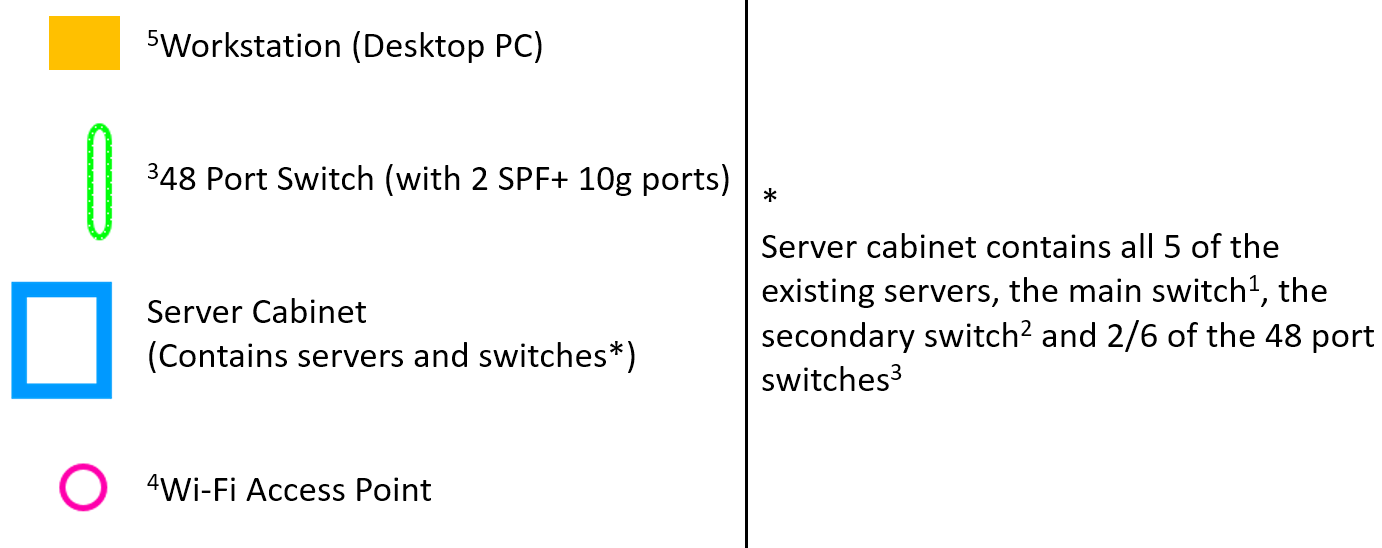
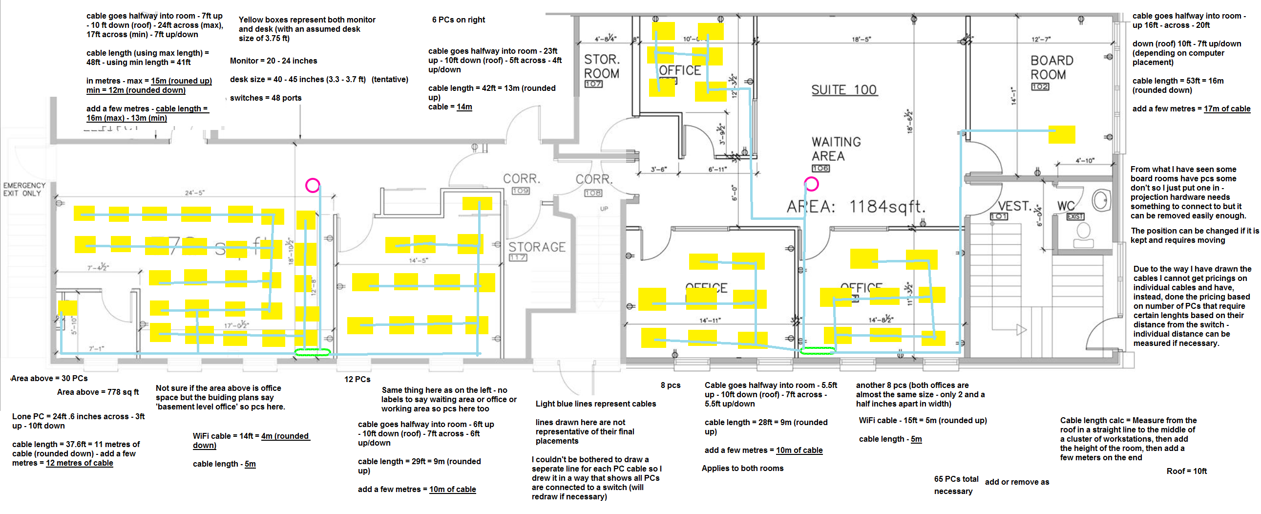
Employee Computers position needs to be worked out, and cable length needs to be calculated Details below. Workstation positions need to be worked out, as well as length of each cable that goes to the switch.
- No more than 94 computers per floor.
- No more than 47 computers per switch.
- Cat5e or better cable needs to be used. (so cat6, cat6a, cat7 are also good, standard cat5 is bad).
- One cable per computer.
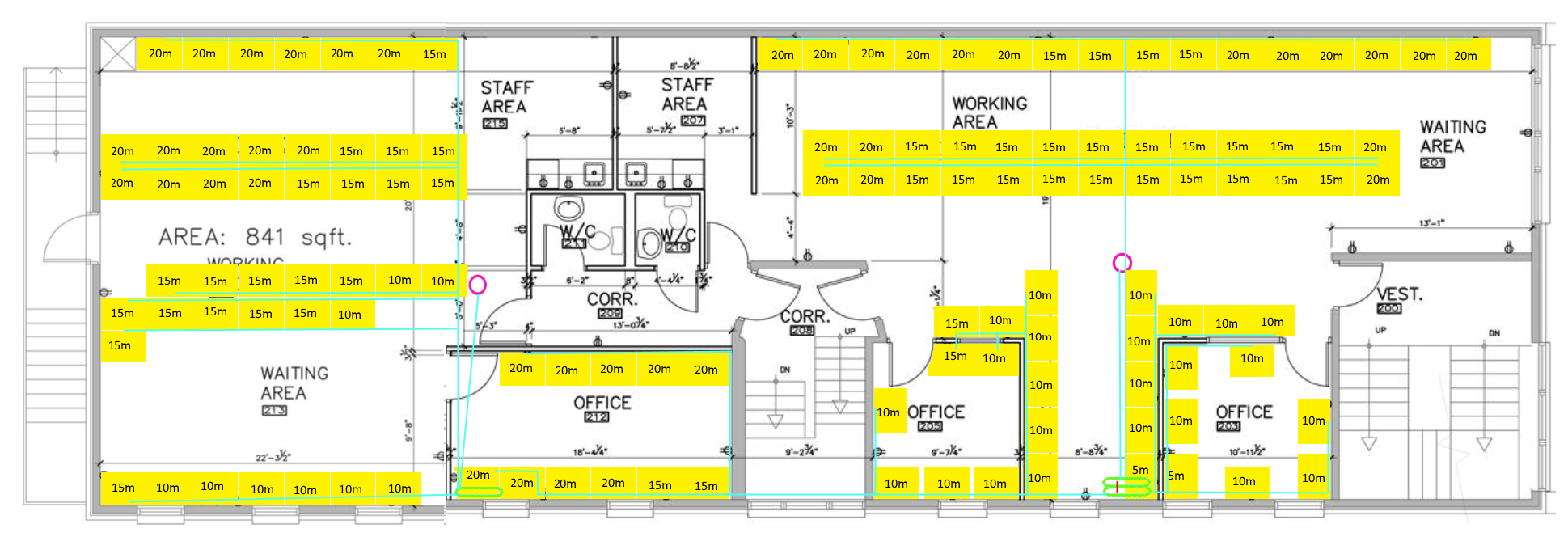
- Length of runs along floor, up walls, and along ceiling to each switch must be accounted for.
- Switches are at the top corner of the south wall of the building
Use a yellow box to represent a computer, and a pale coloured line (perhaps light yellow) for a cable.
Ground Floor
Floor One
Floor Two
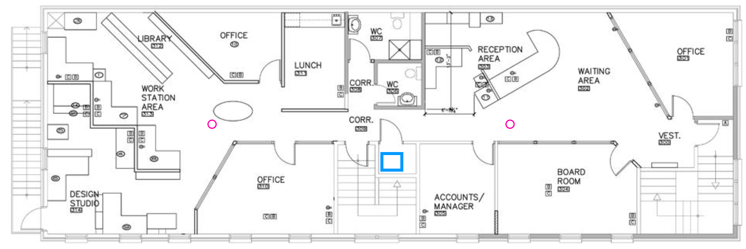

Floor Two
